조명
LED 및 솔리드 스테이트 조명(SSL)은 낮은 에너지 소비, 최신기술 및 긴 수명을 결합한 미래의 빛으로 언급됩니다. LED 및 SSL 제품의 생산 공정에 문제 중 하나는 동일한 생산 배치에서도 밝기, 색상 및 깜박임과 같은 광학 특성의 변화입니다. 조명 제품의 고품질을 보장하기 위해서는 LED 개발 과정에서 이러한 광학 특성을 측정하고 생산 과정에서 100% 검사를 수행해야 합니다. 일반적인 LED – SSL 측정에는 다음이 포함됩니다.
광학 구성 및 구조
| 방사분석 | 분광분석 | 측광분석 | |
|---|---|---|---|
| 적분구 | Radiant power 방사속 [W] | Spectral radiant power 분광 방사속 [W/nm] | Luminous power 광선속[lm] |
| Cosine corrector* 코사인교정기 | Irradiance 방사조도[W/m²] | Spectral irradiance 분광조도[W/m²/nm] | Illuminance 조도[lm/m² = lux] |
| Cosine corrector* 코사인교정기 | Radiant intensity 방사강도[W/sr] | Spectral radiant intensity 분광방사 강도 [W/sr/nm] | Luminous intensity 광도 [lm/sr = cd] |
| 렌즈 | Radiance 방사휘도[W/m²/sr] | Spectral radiance 복사휘도[W/m²/sr/nm] | Luminance 휘도[lm/m²/sr/ = cd/m² = nit] |
*코사인 보정기 대신 적분구를 사용하여 [스펙트럼] 조도 및 복사 강도/조도 및 광도를 측정할 수도 있습니다.
Flicker 측정은 위의 표에 언급된 광학 구성과 조합하여 수행할 수 있습니다.
개별 파장에 대한 광원의 총 방출 전력을 결정하기 위한 스펙트럼 전력 분포 Spectral power distribution 는 예를 들어 색상, CRI, CCT 등과 같은 정보를 나타냅니다. mW/m²/sr, W/m² 및 W/sr 단위의 복사 전력량과 매개변수를 측정하기 위한 복사, 조도 및 복사 강도 Radiance, irradiance & radiant intensity 측정.휘도, 조도 및 광도 Luminance, illuminance & luminous intensity 측정을 통해 광 출력을 cd/m² , Lux 및 cd 로 각각 결정합니다. 광원의 Flicker 측정: Flicker %, Index 및 IEEE 1789 표준.
2D 발광 표면의 측정 2D luminous surfaces 은 대형 발광 패널 또는 표면의 균일성(Uniformity)과 표면검사를 결정합니다.
How are you measuring?
With fibers and other accessories even more type of measurements are possible. Often used accessories are integrating spheres, cuvettes for fluids, light sources or filter holders.
A cosine corrector collects the light from the half space under 180 degrees. A typical application is the illuminance measurement of a lighting situation.
Consumers are used to enjoy top-quality displays in their mobile phones, tablets, laptops and even cars. Emerging technologies such as lighting surfaces for office and home illumination are expected to look equally perfect. Both displays and luminous surfaces are the main application areas for imaging colorimeters.
Measuring the luminance or color values at a specific location of the device under test is a typical use case when measuring displays. It can, however, also be meaningful to assess reflected light.
PCM2X-271

0.000 025 - 30 000 cd/m²
PCM2X-270
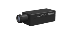
0.000 05 - 60 000 cd/m²
PCM2X-102

0.000 05 - 60 000 cd/m²
PCM2-100
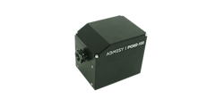
0.0003 - 15 000 cd/m²
Viewfinder Spectrometer

Standard lens 1.2° spot ⌀ 4.56 mm ‑ 6.71 m
Viewfinder Spectrometer

Close up lens 0.75° spot ⌀ 0.96 ‑ 1.47 mm
Colorimeter 2.1 mm
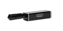
0.001 - 30 000 cd/m² (190 000 cd/m² in UHL mode)
Colorimeter 5 mm

0.001 - 30 000 cd/m² (190 000 cd/m² in UHL mode)
Colorimeter 10 mm

0.001 - 30 000 cd/m² (190 000 cd/m² in UHL mode)
Colorimeter 10 mm wide-angle

0.0003 - 7 500 cd/m² (190 000 cd/m² in UHL mode)
Colorimeter 20 mm

0.0003 - 7 500 cd/m² (48 000 cd/m² in UHL mode)
Colorimeter 27 mm wide-angle

0.0001 - 2 800 cd/m² (20 000 cd/m² in UHL mode)
Spectrometer
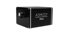
VIS 380 - 780 nm
High-end Spectrometer

VIS 360 - 940 nm


